
Ruby & LGPIO on Orange Pi Zero 2W
Whether you’re getting started with electronics, want to prototype projects more quickly, or just want to use Ruby for something different, a single board computer (SBC) is a great choice.
In this post, we’ll set up Ruby on an Orange Pi Zero 2W, then install the lgpio gem to use its GPIO, I2C, and SPI interfaces.
Orange Pi Zero 2W
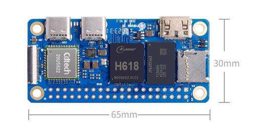
- ~ $21 USD (1GB version)
- Quad-core, 1.5 GHz, ARM Cortex-A53 processor
- 1 / 1.5 / 2 / 4 GB RAM versions available
- Built-in Wi-Fi and Bluetooth
- 40-pin GPIO header, including 3x I2C and 1x SPI
- Official (Debian) and DietPi Linux images available
- User Manual
Step 1: Install DietPi
Orange Pi has an official image for this board, but DietPi is more up to date and less bloated, so we’ll use that instead.
- Download the DietPi image for the Orange Pi Zero 2W
- Downlaod balena Etcher
- Flash the image onto your microSD card using Etcher
- Remove and reinsert the card, so it mounts as an external drive
- On the card, in
dietpi.txt:- Set
AUTO_SETUP_NET_WIFI_ENABLEDto1
- Set
- In
dietpi-wifi.txt:- Set
aWIFI_SSID[0]to your Wi-Fi network name - Set
aWIFI_KEY[0]to your Wi-Fi network password
- Set
- Insert the microSD card into the Zero 2W and connect power
- Find its IP address on your local network (Angry IP Scanner)
- For initial setup, connect as root:
ssh root@<IP_ADDRESS_OF_YOUR_PI>- Password:
dietpi
- Follow the instructions to complete initial setup, selecting
avahi-daemonfor auto installation. You may disable the Serial/UART device when prompted. - Disconnect from this SSH session
- For the remaining steps, connect with:
ssh dietpi@DietPi.localorssh dietpi@<IP_ADDRESS_OF_YOUR_PI>
For more information, see the official DietPi installation guide.
Step 2: Install Ruby
sudo apt install ruby ruby-dev build-essential
Step 3: Install LGPIO C Library
sudo apt install swig python3-dev python3-setuptools

wget https://github.com/vickash/lg/archive/refs/heads/master.zip
unzip master.zip
cd lg-master
make
sudo make install
Step 4: Install lgpio Gem
sudo gem install lgpio
Step 5: Enable I2C and SPI
By default, all pins are set to GPIO, and the I2C and SPI interfaces are disabled, but dietPi makes this easy to change with a configuration file.
sudo nano /boot/dietpiEnv.txt
On the line beginning with overlays=, append device tree overlay names (space delimited) to enable interfaces as needed.
For example, the line below enables the SPI1 interface (with CS0 only), and the I2C1 interface, my setup for development.
overlays=spidev1_0 i2c1-pi
On the Orange Pi Zero 2W, these are the available SPI and I2C overlays, and pins they use (see pinout in Step 7):
spidev1_0(SPI1_CLK, SPI1_MOSI, SPI1_MISO, SPI1_CS0)spidev1_1(SPI1_CLK, SPI1_MOSI, SPI1_MISO, SPI1_CS1)i2c0-pi(TWI0_SCL, TWI0_SDA)i2c1-pi(TWI1_SCL, TWI1_SDA)i2c2-pi(TWI2_SCL, TWI2_SDA)
Note 1: When you enable a SPI or I2C (or UART) interface, the pins used by that interface cannot be used for GPIO until you disable it and reboot.
Note 2: The Zero 2W appears to have 3 internal I2C interfaces assigned /dev/i2c-0 through /dev/i2c-2. As a result, the lowest numbered interface you enable will be appear as /dev/i2c-3, then /dev/i2c-4, and so on.
For example, in my config above, overlay i2c1-pi becomes /dev/i2c-3.
Step 6: Get Permission
We have GPIO, I2C and SPI enabled, but that doesn’t mean we can use them. By default, only the root user has permission. There are other ways to handle this, but Udev rules have been reliable for me.
Create 3 files, with one rule each, as shown below (requires sudo).
# In /etc/udev/rules.d/97-gpio.rules:
SUBSYSTEM=="gpio*", ACTION=="add", PROGRAM="/bin/sh -c 'chgrp gpio /dev/gpiochip0 && chmod g+rw /dev/gpiochip0'"
# In /etc/udev/rules.d/98-i2c.rules:
SUBSYSTEM=="i2c*", ACTION=="add", PROGRAM="/bin/sh -c 'chgrp i2c /dev/i2c-* && chmod g+rw /dev/i2c-*'"
# In /etc/udev/rules.d/99-spi.rules:
SUBSYSTEM=="spidev*", ACTION=="add", PROGRAM="/bin/sh -c 'chgrp spi /dev/spidev* && chmod g+rw /dev/spidev*'"
On each boot, these will ensure the GPIO, I2C and SPI devices belong to groups we specify, and they have have read+write acces.
Now we need to create those groups, and add our user to them:
sudo groupadd gpio
sudo groupadd spi
sudo groupadd i2c
sudo usermod -aG gpio $(whoami)
sudo usermod -aG i2c $(whoami)
sudo usermod -aG spi $(whoami)
Reboot so changes from this step, and the previous, will take effect.
Step 7: Test It
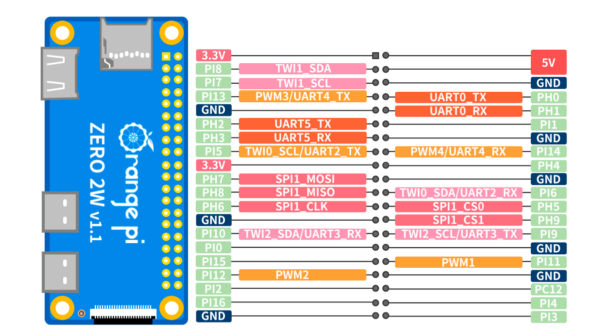
Orange Pi Zero 2W Pinout:
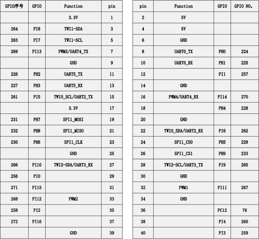
Orange Pi Zero 2W GPIO Numbers:
A blinking LED is the “Hello World!” of hardware, so let’s try that:
- Connect the positive side of an LED to GPIO 260, and its negative side to any GND, through an appropriate resistor.
- Save the blink example from the
lgpiorepo asblink.rb. - Run
ruby blink.rband your LED should start blinking.
Follow the scripts in the examples folder to learn more.